BL10U
INFORMATION
Experimental Techniques
Standard Measurement
- - Monochromatic μ-CT
- - Ultra-small-angle X-ray scattering (USAXS)
Advanced Measurement
- - X-ray photon correlation spectroscopy (XPCS)
- - X-ray ptychography
Overview
This beamline utilizes monochromatic X-rays obtained by a double-crystal monochromator with an undulator as the light source. It covers the range from tender X-rays to hard X-rays.
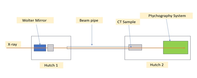
There are two experimental hutches. The first hutch, located 35 to 40 meters from the light source, is equipped with a Wolter mirror, allowing for the use of a microbeam (horizontal: 11 μm, vertical: 0.7 μm (design values)). It is anticipated that the commissioning of the Wolter mirror will take some time. We will announce on our website when it becomes available.
The second hutch is situated approximately 49 to 57 meters from the light source. A fixed table at the front of this hutch enables monochromatic X-ray CT measurements. The maximum sample diameter is slightly less than 1 mm . High-resolution monochromatic projection imaging is also possible. For both CT and projection imaging, increasing the distance between the sample and the detector allows for edge enhancement using refraction contrast and phase imaging through phase retrieval.
Downstream of the second hutch, a ptychography system is installed, enabling high-resolution X-ray imaging. Please consult Professor Yukio Takahashi, SRIS for inquiries regarding this technique.
The first and second experimental hutches are connected by an approximately 9-meter vacuum pipe. By placing the sample in the first hutch and the detector in the second hutch, advanced measurements such as XPCS and USAXS can be performed. For these techniques, please consult Associate Professor Taiki Hoshino, SRIS.
Please note that for advanced measurements, the setup and alignment of equipment may take time, which will be included in the user's beamtime.
Beam Characteristics
- Energy 2.1~18.3 keV
- Flux 1.6~12 x 1011 cps (Calculated value, depends on energy and experimental conditions)
- Beam size In experimental hutch 2, the beam size is approx. 1 mm (horizontal) x 0.5 mm (vertical) (FWHM).
Hutch size
Experimental Hutch 1: Approx. 6 m (length) x 4 m (width) x 4 m (height)
Experimental Hutch 2: Approx. 10 m (length) x 4 m (width) x 2.8 m (height)
Light Source and Optics
This beamline utilizes a 166-pole, 22 mm period in-vacuum undulator as its light source, and a monochromatic X-ray beam is available after passing through a liquid nitrogen-cooled Si(111) double-crystal monochromator. A set of three total reflection mirrors is installed upstream of the monochromator, allowing for harmonic rejection without changing the beam height. Downstream of the monochromator, there is a cross slit, which can be used as a virtual source for measurements requiring coherence.
Experimental Station
-
Equipment
Hutch 1: [Wolter Mirror] (Focusing size: H 11 µm, V 0.7 µm)
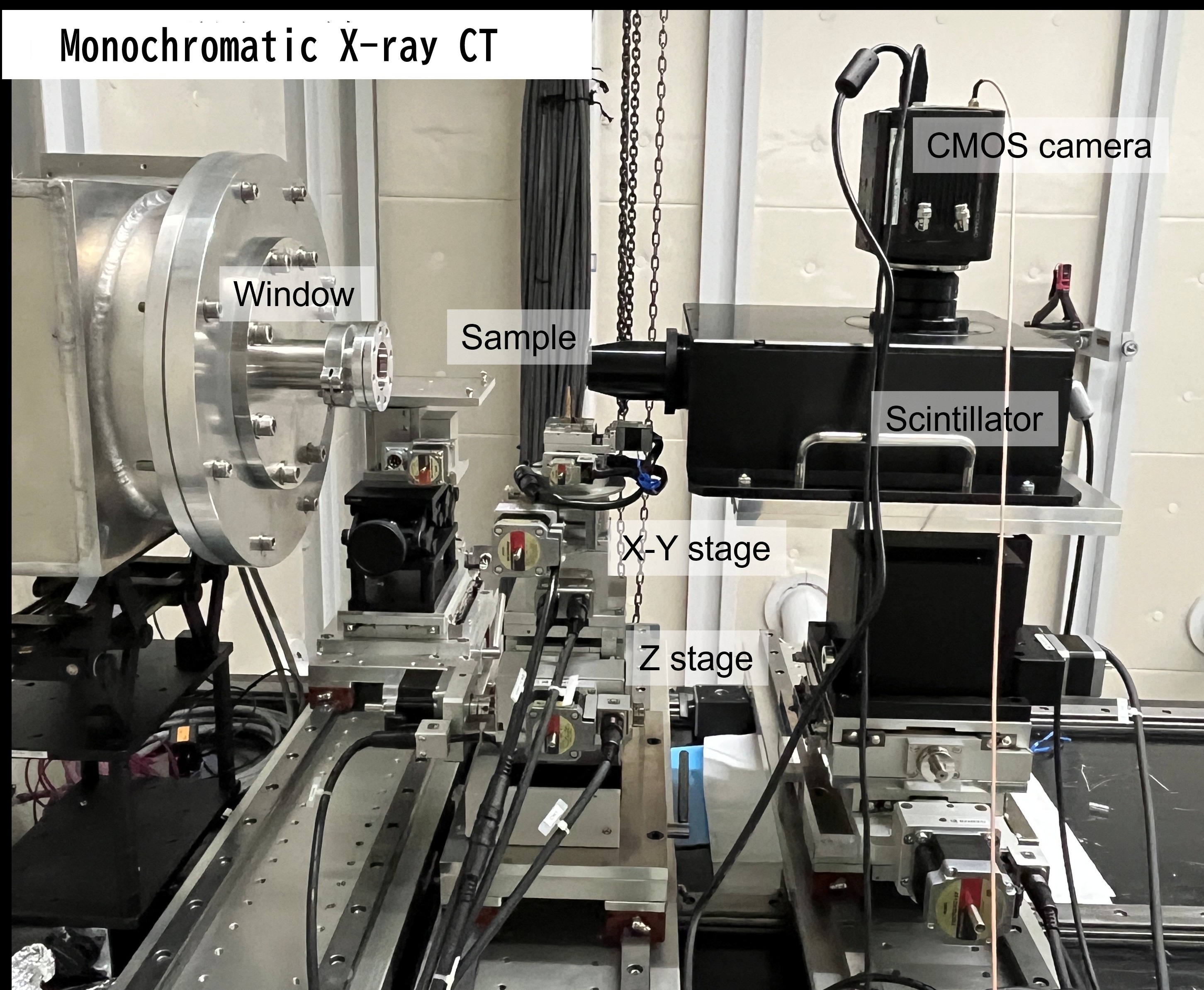
Hutch 2: [High-Resolution CT Imaging System]
Hutch 2: [X-ray Ptychography System] -
Detector
[High-Resolution Visible Light Conversion X-ray Detector]
Hamamatsu AA-51 / ORCA-Flash 4.0 (Pixel: ~0.5 µm)
Layout
Detailed Information by Measurement Method


Monochromatic X-ray CT Basic Information
- Field of ViewApprox. 1 mm (horizontal) x 1 mm (vertical)
- Spatial ResolutionApprox. 1 μm
- Pixel Size0.65 μm
- Data Volume65 GB per sample (SSD with 1000 MB/s recommended)
- EnergySelectable between 6 keV and 18.3 keV (Typically 8.3 keV or 15 keV)
- Sample SizeIdeally cylinder < 1 mm dia. or prism < 1 mm side
- Method180° rotation in 0.1° increments (1801 projections)
Measurement Examples (High-Resolution CT)
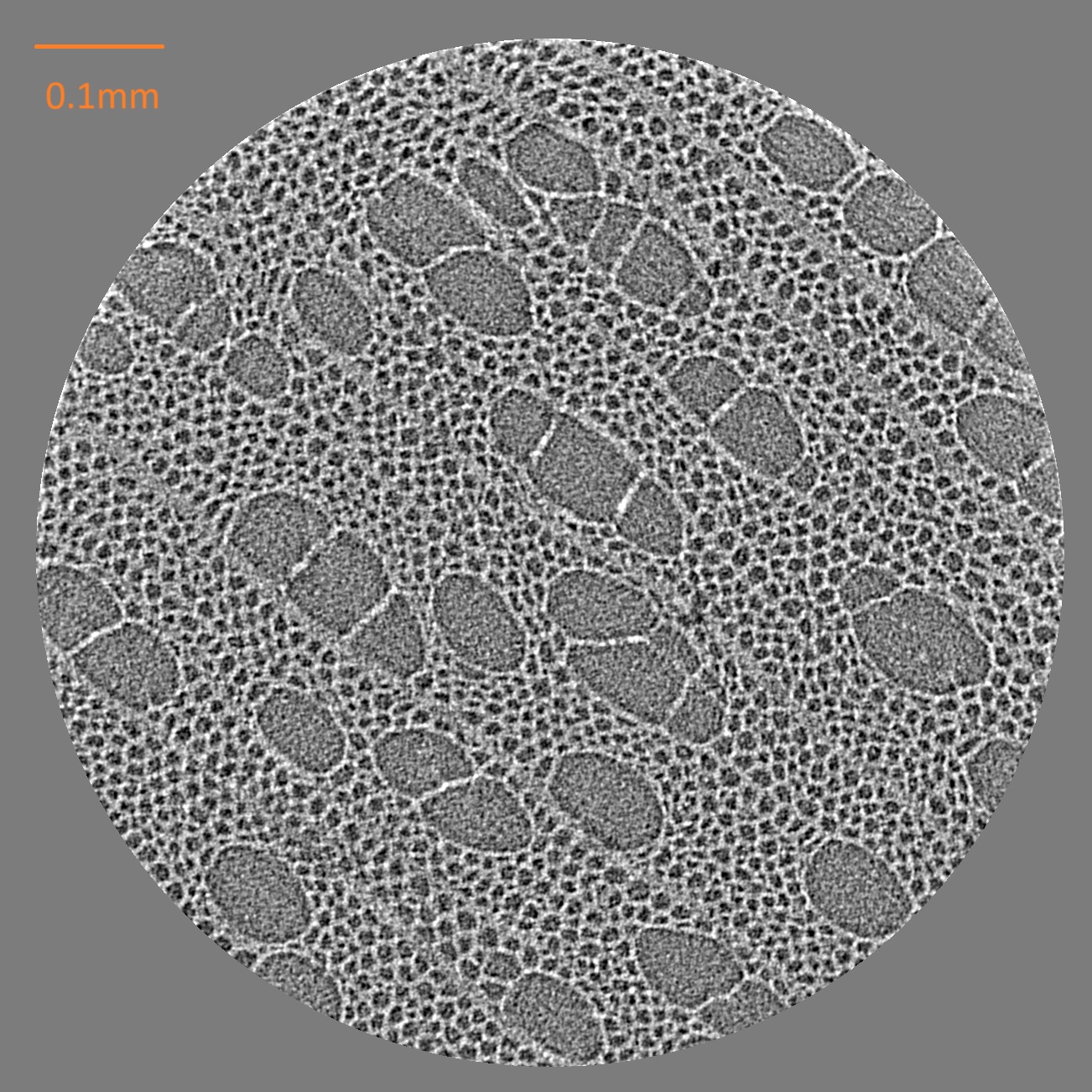
- SampleToothpick
- Exposure100 ms/projection
- Energy15 keV
- Pixel Size0.65 μm
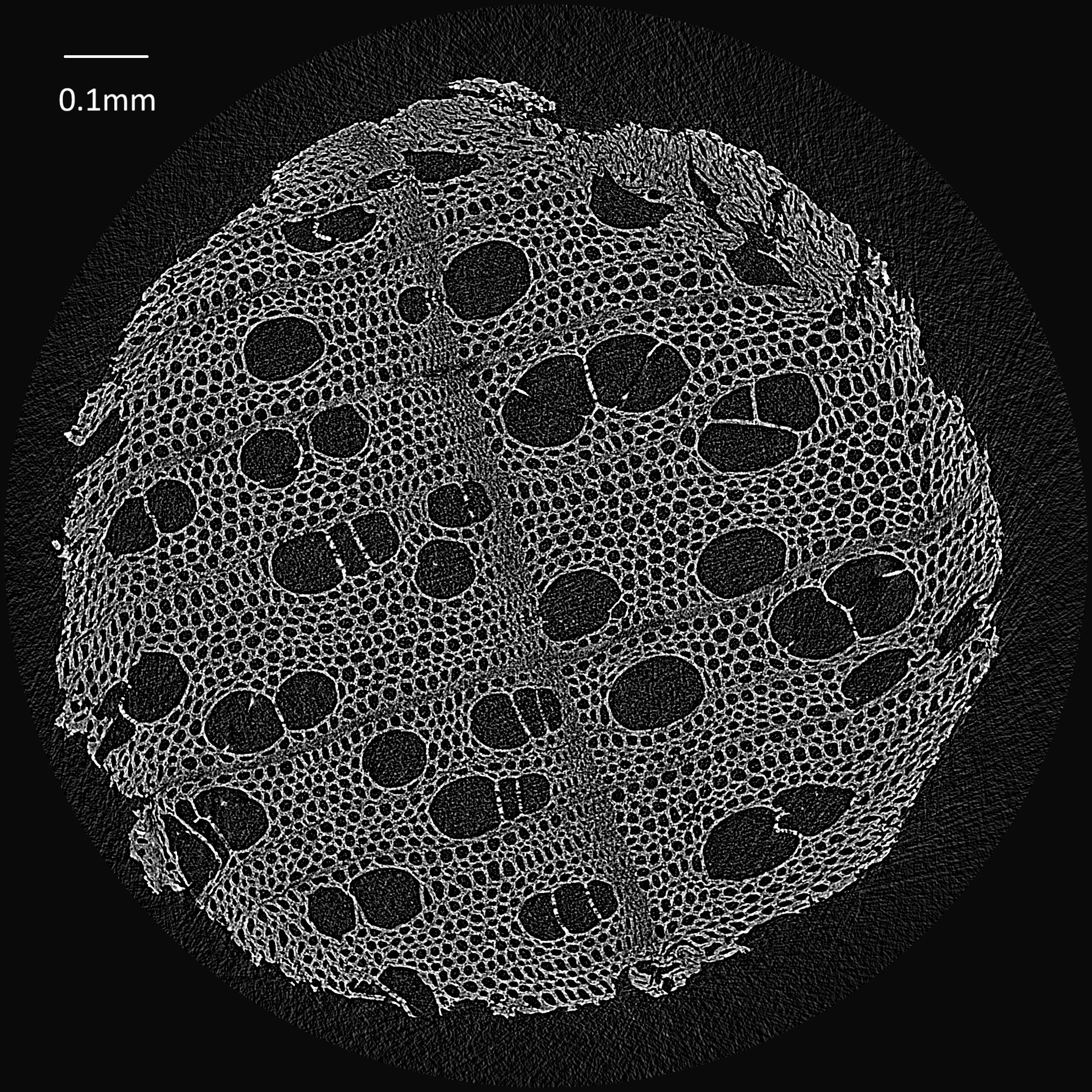
- SampleToothpick
- Exposure100 ms/projection
- Energy9 keV
- Pixel Size0.65 μm
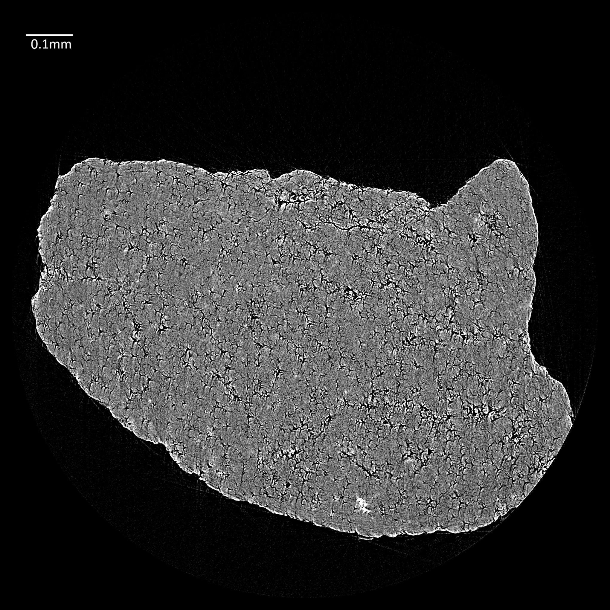
- SampleSand grain
- Energy15 keV
- Pixel Size0.65 μm
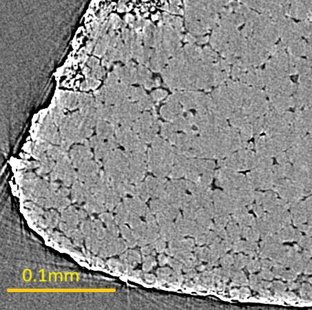
- SamplePiece of rice
- Energy15 keV
- Pixel Size0.65 μm