BL09W
INFORMATION
Experimental Techniques
- White-beam wide-field CT
- White-beam μ-CT
- 4D-CT (Advanced measurement)
【Coalition Conference's Lecture】 (Japanese)
*Please note that the above lecture materials are based on information as of December 5, 2023, and some technical details may have been updated since then.
Overview
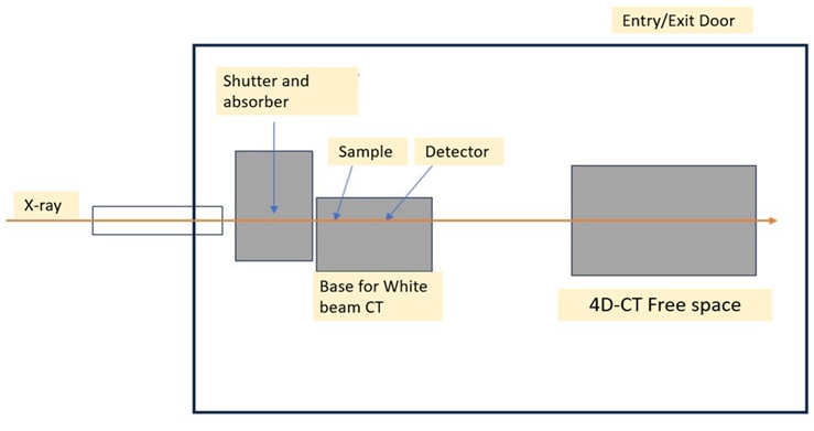
This beamline utilizes a multipole wiggler as its light source and provides a white X-ray beam in the energy range of 4 keV to 30 keV. (Energies below 4 keV are cut off by a Be window, and those above 30 keV are cut off by a flat mirror.) A beam with a maximum size of approximately 50 mm (horizontal) by 4 mm (vertical) is available. A white X-ray CT system is installed upstream in the experimental hutch as a standard measurement setup.
The downstream part of the hutch is a free space, allowing for 4D-CT, which adds a time axis to conventional 3D-CT. As 4D-CT is an advanced measurement, please consult with Professor Wataru Yashiro of SRIS.
Please note that the time required to bring in and set up equipment within the hutch is included in the allocated beamtime.
Beam Characteristics
- Energy 4 to 30 keV white beam (continuous spectrum with maximum intensity around 20 keV)
- Flux 3.0 x 10¹⁶ cps (calculated value)
- Beam size Max. width 50 mm, height approx. 4 mm
Hutch size
Dimensions: 8 m (along the beam axis) x 5 m (width) x 4 m (height) (A free space of 3 m x 3 m with a height of 3.3 m is available for users.)
Light Source and Optics
This beamline utilizes a 5-pole multipole wiggler as its light source, and the beam is reflected upwards by a flat mirror. The cutoff energy of the mirror is around 30 keV.
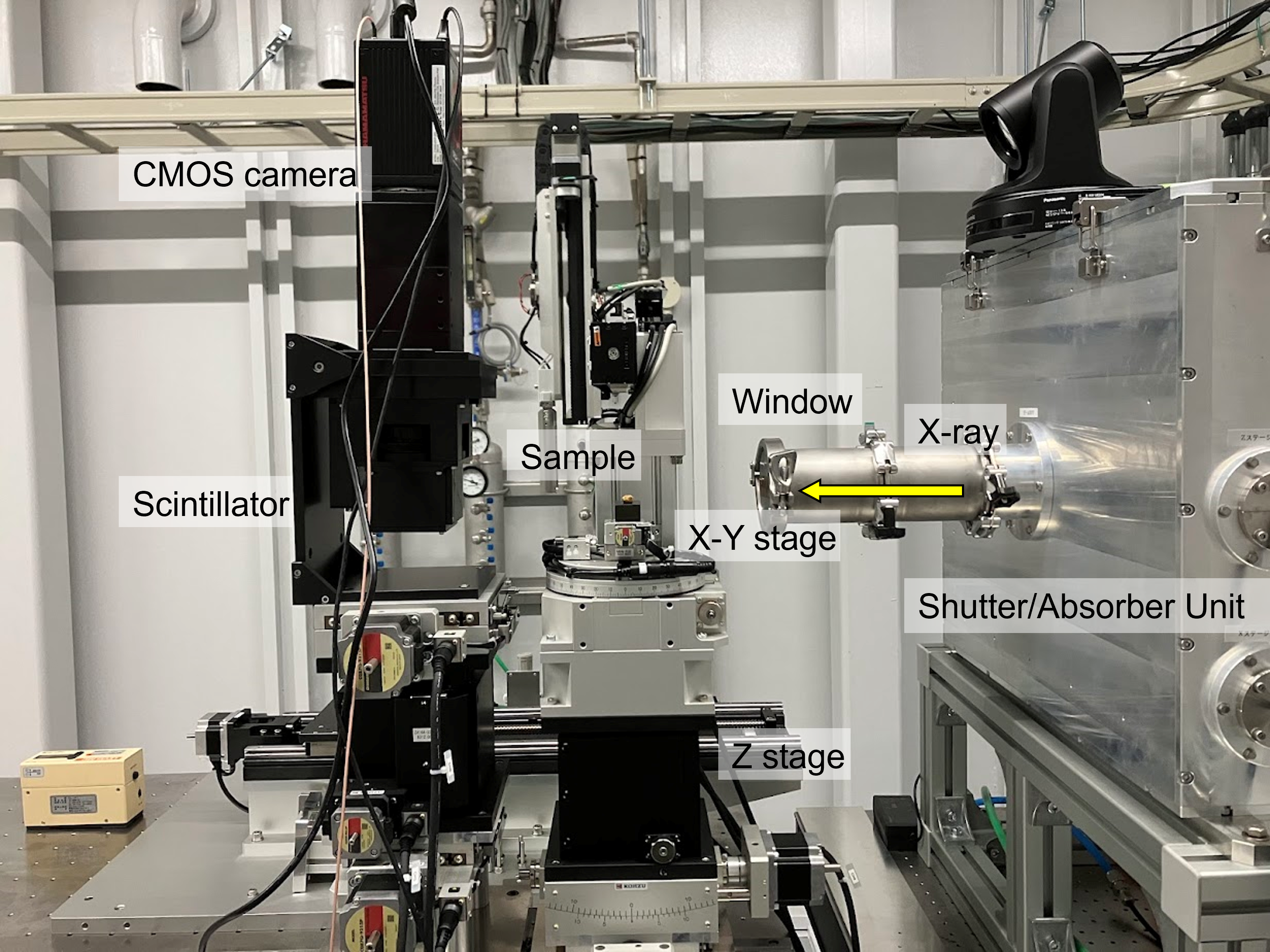
Experimental Station
Standard Measurement 【White X-ray CT Imaging System】
- Imaging field of view: Approx. 20 mm (horizontal) x 4 mm (vertical)
- Scintillator: LuAG (Ce-doped), 0.2 mm thickness
- Detector: Digital CMOS camera C16240-20UP (Hamamatsu Photonics)
- Camera pixel size: 4.6 μm
- Stage load capacity: 4 kgf
- Sample-to-detector distance: 0.15 - 1.0 m
By increasing the distance between the sample and the detector, edge-enhanced imaging using phase contrast is possible.
Layout
Measurement time and data size
Per standard measurement (180-degree scan, 0.1-degree step, 1800 projections):
- Measurement time: Approx. 15 minutes
- Data size: Approx. 112 GB
On average, approx. 20 samples can be imaged per 8-hour shift.
Please bring a USB storage device with a capacity of 2 TB or more.
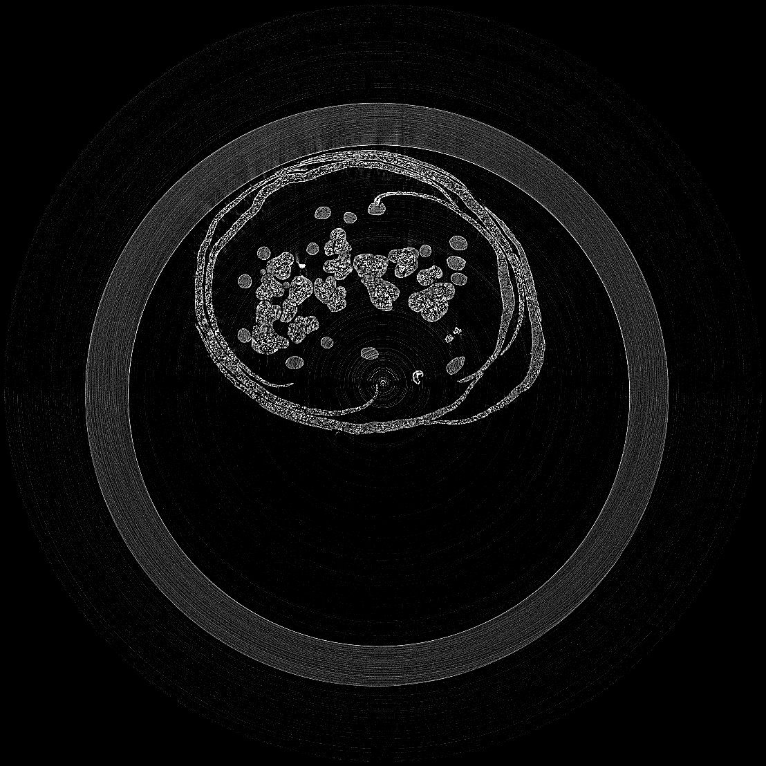
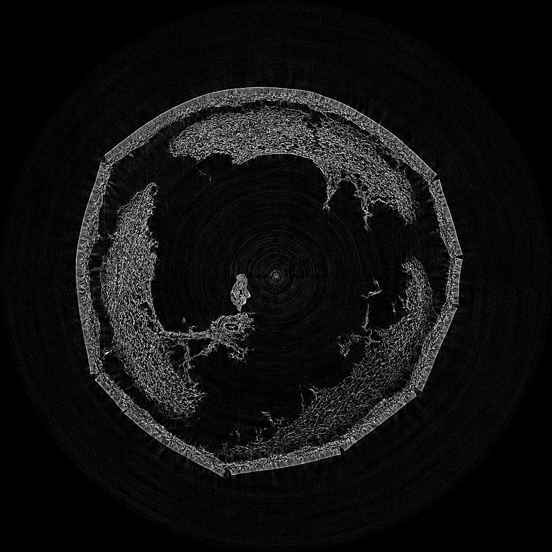
CT imaging measurement examples using BL09W
Is there anything that looks like stamen pollen that we can see?
- SampleBud of a tree flower
- Exposure time60 ms/projection
- Number of projections1800 (total approx. 5 min)
- Sample-to-detector distance150 mm
- X-ray energyWhite X-ray (20 mm Al absorber)
- Pixel size5 μm
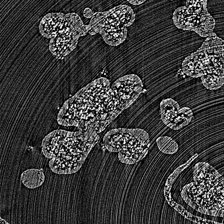
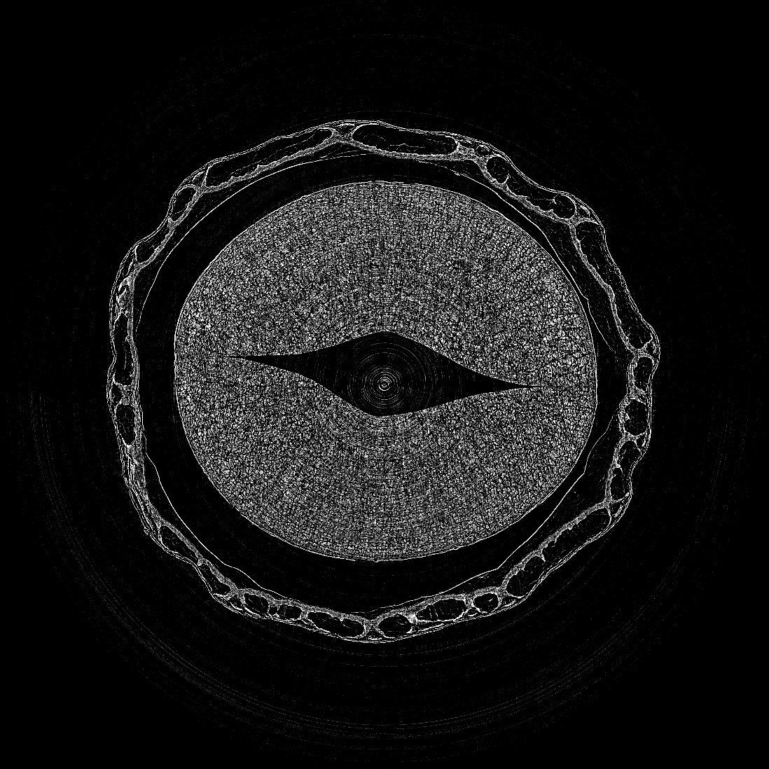
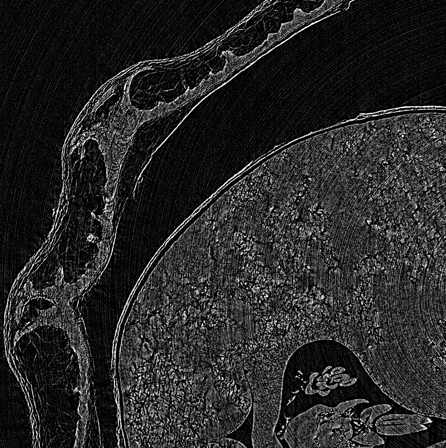
Equivalent to the first enlarged image (No binning)
- SampleBud of a tree flower
- Exposure time60 ms/projection
- Number of projections1800 (total approx. 5 min)
- Sample-to-detector distance150 mm
- X-ray energyWhite X-ray (20 mm Al absorber)
- Pixel size5 μm
- SampleAcorn
- Exposure time60 ms/projection
- Number of projections1800 (total approx. 5 min)
- Sample-to-detector distance150 mm
- X-ray energyWhite X-ray (20 mm Al absorber)
- Pixel size20 μm
- SamplePeanut
- Exposure time60 ms/projection
- Number of projections1800 (total approx. 5 min)
- Sample-to-detector distance150 mm
- X-ray energyWhite X-ray (20 mm Al absorber)
- Pixel size20 μm
Another slice of the imaging result of a peanut (no binning)
- SamplePeanut
- Exposure time60 ms/projection
- Number of projections1800 (total approx. 5 min)
- Sample-to-detector distance150 mm
- X-ray energyWhite X-ray (20 mm Al absorber)
- Pixel size5 μm