BL08W-XRD
INFORMATION
Notice of Restricted Spinner Use (May 27, 2026)
Due to upgrades being made to the spinner, experiments requiring its use will be unavailable from July 28 to September 30.
Please note that XRD/XRF experiments using the XZ stage can still be conducted during this period.
We apologize for any inconvenience this may cause to users who were planning experiments with the spinner, and we appreciate your kind understanding.
Experimental Techniques (All are standard measurements)
- X-ray Powder diffraction
- 2D X-ray diffraction mapping (Prior consultation with PhoSIC is required)
- Surface X-ray diffraction (Prior consultation with PhoSIC is required)
- In-situ X-ray diffraction (Prior consultation with PhoSIC is required)
- Element mapping using X-ray fluorescence (Prior consultation with PhoSIC is required)
Overview
This hutch is equipped with a general-purpose X-ray diffractometer. Powder diffraction measurements of samples enclosed in capillaries are possible using a capillary spinner for powder diffraction and a two-dimensional (2D) detector (standard measurement). Mail-in measurements are also accepted.
Furthermore, it is possible to perform diffraction mapping and in-situ experiments. Diffraction mapping involves placing a sample on the general-purpose sample stage and moving it horizontally and vertically to record diffraction patterns at each point. In-situ experiments involve measuring diffraction patterns while changing the sample's environment. Users must bring their own equipment for controlling the sample environment. Usable gases are limited to harmless gases, such as N2 and CO2. Surface X-ray diffraction is performed by placing a sample on the powder diffraction spinner and controlling the angle for measurement. For these specialized measurements, please consult with the PhoSIC staff before booking beam time.
2D elemental mapping using X-ray fluorescence is performed by placing a sample on the general-purpose sample stage and moving it horizontally and vertically to detect X-rays at each point.
Light Source and Optics
The branchline for XRD measurement provides monochromatized X-rays. A white X-ray beam generated by a 5-pole multipole wiggler light source is monochromatized using Bragg reflection from a Si crystal and is split off-axis from the original beam. The X-ray energy can be selected by choosing either the Si(111) or Si(220). Focusing is performed by a bent cylindrical mirror.
Beam Characteristics
-
Energy
17.5 keV or 28.5 keV
The default energy is 17.5 keV, and we can accommodate 28.5 keV upon request. Please specify the desired energy when making your beamtime reservation.
We do not switch the energy during beamtime, as it may affect other branches. -
Flux
Example of an actual measurement value at a storage ring current of 200 mA
17.5 keV 1.2 x 10¹¹ cps
28.5 keV 7.0 x 10⁹ cps -
Beam size
Example of an actual measurement value at the powder diffractometer sample position:
120 μm(horizontal)、70 μm(vertical) - Hutch size Approx. 3m (optical axis direction) x approx. 2m (width) x approx. 3.3m (height)
Experimental Station
[Spinner for powder samples]
- • Sample-to-detector distance: approx. 240 to 890 mm
- • Measurement range: 2 Θ < 50 degrees (For 17.5 keV, it is equivalent to CuKa at 133 degrees)
- • Powder and liquid samples can be sealed in a capillary 【Example of how to prepare a capillary sample】
- • The sample holder is equivalent to those of SPring-8 BL19B2 and AichiSR BL5S1.
- • CeO2 and Si are available as standard samples.
- • The rotation axis can use a camera-based automatic alignment mechanism.
- • Several software packages for converting data to 1D are available. However, analysis software, including for the "Rietveld method", is not installed. Please ask a staff member regarding the application of the Rietveld method.
[Large Area IGZO Flat Panel Detector]
Hamamatsu Photonics K.K. C14406DK-2918
- • Detection area: 430 x 430 mm
- • Pixel size: 140 μm²
- • Scintillator: Directly deposited CsI
- • Frame rate: Maximum 15 fps (full frame)
- • Dynamic range: 87 dB
[General Purpose X-Z Stage]
Kohzu Precision Co., Ltd. XA07A-L202 and ZA07A-V1F01
- • Sample-detector distance: Approx. 100 ~ 580 mm (Adjustable by lab jack)
- • Three types of user cables (one BNC, one LAN, and three USBs) are available for use inside and outside the experimental hutch. If you wish to use them, please inform us when making your reservation.
- Please note that in the case of USB cable connections, it is possible that the equipment may not operate properly depending on your device. Please consider necessary countermeasures in advance.
- • Other types of automated stages are also available. Please consult with us if you wish to use them.
[Fluorescent X-ray analysis and elemental mapping by fluorescent X-ray]
TechnoAP Co., Ltd. Single-element silicon drift detector XSDD30-01GRCL-ICF
• The sample is set on the X-Z stage tilted at a horizontal 45-degree angle to the X-rays, and fluorescent X-ray are detected in the 90-degree direction.
• Effective area: 28 mm²
• Window: Graphene
• Maximum count rate: 1 Mcps
• Cooling: Peltier element
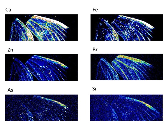
Because measurements are taken in the atmosphere, absorption of fluorescent X-rays by the air occurs. Therefore, elements heavier than sulfur (mainly transition metals) are the subjects of measurement. For elemental mapping, the sample is moved on the X-Z stage to scan the sample with X-rays. After measuring at each position, the fluorescent X-ray spectrum (MCA data) is read. The time required for data reading and moving the sample stage is 0.2 to 0.3 seconds. The data accumulation time at each position depends on the concentration of the target element.
Software for visualizing element distribution is available.
As described above, since the size of the X-ray beam is approximately 100 μm, the maximum spatial resolution is also about the same.
[Others]
For sample alignment, a web camera and a laser coaxial with the X-ray are available.
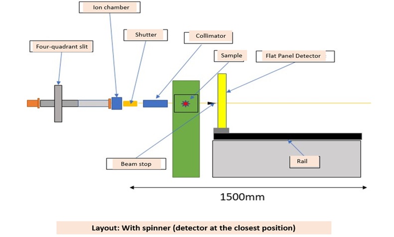
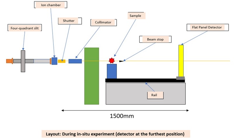
Layout
With spinner (detector at the closest position)
During in-situ experiments (detector at the furthest position)
Measurement Examples
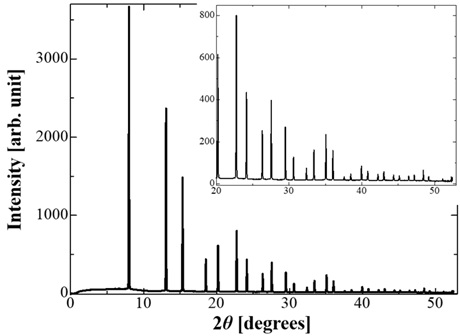
Si powder diffraction pattern
28.5 keV / Sample - Detector distance 235 mm / 5-second exposure
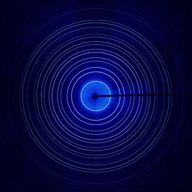
* Analysis of powder diffraction data obtained by the flat panel detector using the Rietveld method is currently under consideration. (Please contact a staff member for details.)
Fluorescent X-ray elemental mapping of a moth's wing
17.5 keV / Horizontal 71 μm / Horizontal 300 points with vertical 100 μm steps / Total 33,000 points / 1 second accumulation per point